

RFQ

HIP Technology

Hot Isostatic Pressing: close internal defects with heat and isostatic gas pressure

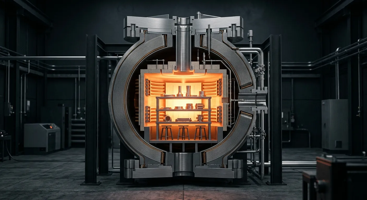
HIP combines temperature, isostatic gas pressure, and hold time in a controlled cycle that closes pores, microcracks, and lack-of-fusion defects through plastic yielding, creep, and diffusion.

Cutaway illustration of the internal structure of a HIP vessel
HIP vessel cutaway

Learning Path

Process Understanding Path

  1. HIP Fundamentals
  2. Technical Glossary
  3. HPHT / URC / URQ
  4. Technical Articles

Process Sequence

HIP process flow: six stages from loading to unloading

Loading, evacuation or purging, heating, pressurization, holding, controlled cooling, depressurization, and unloading form a traceable process sequence tied to cycle time and quality records.

Six-step hot isostatic pressing process background
Load / Heat / Pressurize / Hold / Cool / Unload

Cycle Curve

Process window defined jointly by pressure, temperature and time

A representative process profile is more useful than a decorative curve. The diagram below illustrates heating, pressurization, holding, and controlled cooling with example data.

HIP Process Cycle DiagramTypical three-parameter pressure/temperature/time curve
LoadHeat + pressurizeHoldControlled cooling
PhaseTimeTemperaturePressure
Load & purge0 h25°C0.1 MPa
Heat & pressurize2 h900°C60 MPa
Hold4 h920°C100 MPa
Controlled cooling6 h420°C80 MPa
Depressurize & unload8 h80°C0.1 MPa

This illustrative cycle shows the expected data structure only. Final parameters must be validated for the material, load configuration, usable zone, equipment design, and applicable customer standards.

Pressure Mode

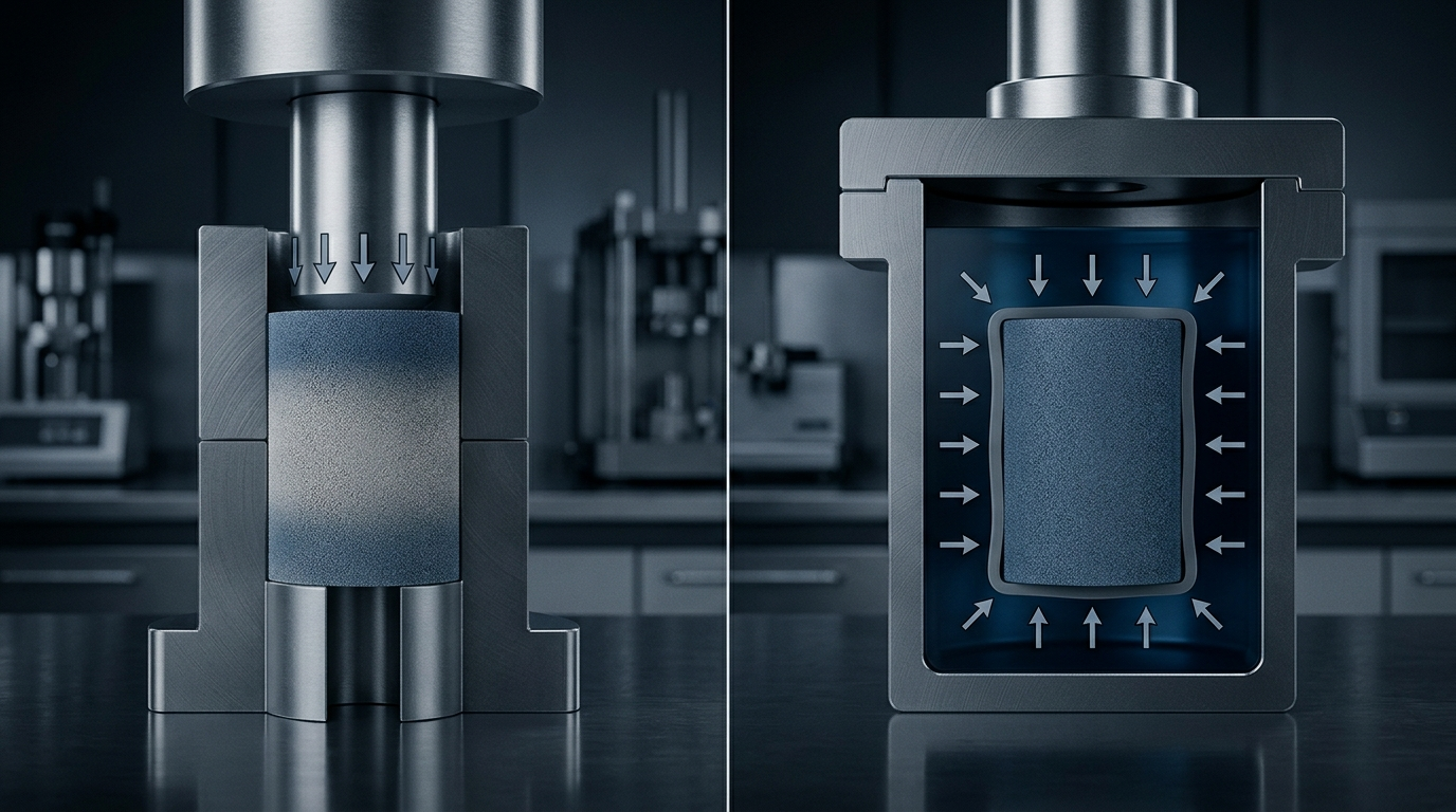
How isostatic pressure differs from uniaxial pressing

Uniform pressure in each direction reduces density gradients and is more suitable for handling complex geometries, internal pores, and highly reliable components.

Process ComparisonIsostatic Pressure Distribution and Controlled Cooling Path

Equipment Preview

Equipment structure and hot zone preview

Relate the pressure vessel, usable zone, loading envelope, and process interfaces to the overall equipment architecture.

Core Equipment

Wire-wound pressure vessel with a configurable usable zone

The wire-wound structure transfers pressure loads into high-strength steel wire layers and is engineered for sustained operation up to 200 MPa. Usable-zone diameters can scale from Ø100 mm laboratory systems to Ø2000 mm production platforms, with the vessel envelope and process interfaces configured for the application and facility.

Technology Modules

Three technical modules that determine the effect of HIP

Uniform pressure, high temperature and high pressure cycling, and controlled cooling together determine the final material properties and equipment selection boundaries.

Comparison between isostatic pressure and uniaxial pressing

Uniform pressure in all directions

High-pressure inert gas, typically argon, acts uniformly on every exposed surface. Because pressure transfer is independent of die-wall friction, HIP avoids the density gradients associated with uniaxial pressing and is well suited to complex cavities and thin-walled geometries.

Dark process dashboard showing pressure, temperature, and time cycle curves

High-Temperature, High-Pressure Cycle

Pore closure is governed by plastic yielding, power-law creep, and diffusion. Pressure, temperature, and holding time together determine final density, diffusion-bond quality, and microstructural evolution; process development is therefore based on a pressure-temperature-time map.

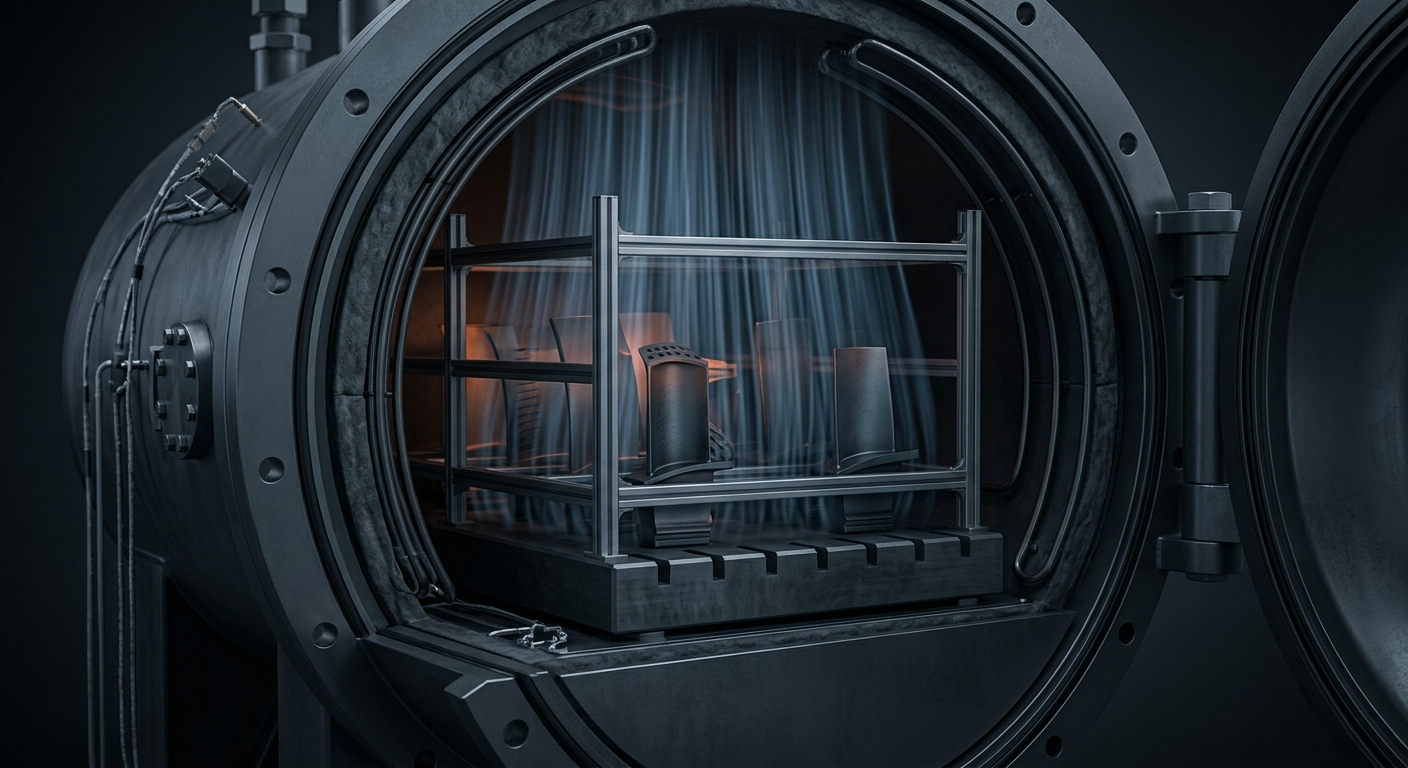
Engineering concept visual for uniform rapid cooling inside a HIP furnace

Uniform Rapid Cooling

Forced convection of high-pressure gas provides faster, more uniform cooling than conventional furnace cooling. The controlled path can reduce distortion and residual stress while enabling integrated HIP and heat-treatment cycles such as HPHT, URC, and URQ.

Material Process Windows

Reference process windows for typical material families

The values of pressure, temperature and holding time of different materials vary greatly, and the following intervals are used to illustrate the typical selection logic.

Material FamilyPressureTemperatureHolding timeProcess Objectives
Titanium alloy (Ti-6Al-4V castings/AM parts)100–103 MPa890–920°C2–4 hClose internal pores and improve fatigue life; ASTM F3301 is a common reference for AM post-processing
Nickel-based superalloy (Inconel 718/625)100–103 MPa1120–1165°C2–4 hDensification with the option to integrate solution treatment into an HPHT cycle
Powder-metallurgy tool steel/stainless steel (H13, 316L)100 MPa1100–1200°C2–3 hNear-net-shape PM-HIP densification without a separate sintering step
Cobalt-chromium alloy (CoCrMo medical implants)100 MPa1150–1200°C2–4 hControlled atmosphere, improved fatigue strength, and repeatable implant batches
Aluminum-alloy castings (Al-Si series)100 MPa480–520°C2–4 hClose microporosity and improve elongation in applications such as aerospace castings

These industry reference ranges illustrate process-window logic only. Final pressure, temperature, holding time, and cooling strategy must be validated for the material grade, manufacturing route, defect type, heat-treatment condition, and applicable customer standards.

CTA Ladder

Move from technical understanding to engineering evaluation

Use the technical articles and material reference windows for your internal review, then submit material parameters for a preliminary process-window assessment.

Home